|
TABLE OF CONTENTS
1) Foreword
2) Preliminary information
3) Common elements to both mod's
4) Needed components and parts
5) Tutorial no.1 (valid on PAL consoles only)
6) Tutorial no.2 (valid on all PAL and NTSC consoles)
7) Credits
1) FOREWORD
This page contains information and tutorials about modding your CreatiVision
console to enhance it with an additional composite video output
feature. This will give you a much better picture than the "standard" one
generated by the internal RF modulator which outputs through the antenna
cable.
The composite video signal doesn't include any audio information
(unlike the RF modulated antenna signal), so you have to set up an
additional audio output to use in combination with the composite video
output.
All information came from my dear friends Gavino Sechi of
Oristano (Italy) and Thomas Gutmeier of Wien (Austria), who are
talented technicians and experts on Creativision repairs.
The first mod (Tutorial no.1) was provided by
Gavino. This mod was actually done to my Hanimex Rameses console which has PCB
model "700319". This is the standard CreatiVision mainboard for use with PAL
televisions from late 1982 onwards. I personally tested this mod and I can
assure you the result is great!
Gavino also provided additional information to make the mod compatible with
consoles based on the "700305" PCB. This PCB model is supplied on older
consoles, also made for use with PAL televisions from 1981 to early 1982.
The second mod (Tutorial no.2) was provided by
Thomas. He did this mod to his own CreatiVision console. Itís a "generic" mod
that can be applied to any CreatiVision regardless of the PCB model.
I have not tested this mod, however I'm sure the information is technically
sound and provides a simpler solution.
2) PRELIMINARY INFORMATION
Prior to going into the details of each tutorial and see how they differ, you
need to know a few facts about CreatiVision hardware.
In PAL models (all except the NTSC Japanese version) you can
adjust the video signal before it reaches the RF modulator. There are three
variable resistors VR1, VR2 and VR3 (called "trimmers" or "pots") which
are mounted in close proximity to the RF modulator. All you have to do is
adjust the setting of the three trimmers by turning them with a small
screwdriver.
While the console is powered on and connected to a TV via the antenna cable,
adjust the trimmers to get a perfect brightness, tint and hue. The trimmers do
not need to be adjusted after the composite video output mod is done.
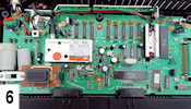
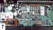
Please refer to the following diagrams to identify the PCB model
in your console.
   
[click pictures to enlarge]
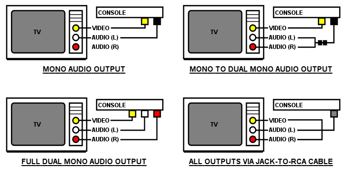
The sound chip generates audio on a single channel
(mono), unlike modern gaming consoles which usually have two channels
(stereo) or more (dolby, optical, etc.).
If you want to connect the console to a modern TV having two audio input RCA
sockets, choose one of the following options:
- using an RCA mono cable, connect the RCA mono output on the
console to one of the TV's RCA stereo inputs (either red or white). In this
case you'll hear sound from just one loudspeaker;
- using either an RCA stereo cable and RCA single to double Y
adapter or RCA single to double cable, connect the RCA mono output on
the console to the TV's RCA stereo inputs (both red and white);
- using an RCA stereo cable, connect the dual mono outputs on
the console to the TV's stereo inputs (both red and white). You can either
use two separate mono sockets, a single stereo socket or a
4-pole 3.5mm socket which will also transmit the video signal.
Please refer to the following diagrams and choose the best for
your situation.
3) COMMON ELEMENTS TO BOTH MOD'S
Before you begin the actual modifications you should make a decision which way
you want to build the outputs; one or more cables with female sockets
or one or more panel mount sockets placed inside the console case.
Case one. First of all, notice that the CreatiVision case
has no holes for cables to go through from the inside of the case to the
outside of the case, other than the one where the antenna is located. You
can either:
- enlarge the hole where the antenna cable passes then let the
composite video cable also pass through the same hole;
- remove the antenna cable permanently and let the composite video
cable pass through the hole by itself (without enlarging it);
- remove the left "wooden" panel and let the cable(s) come out of the
hole in the case where the cassette tape player connector is. If you
choose this method you won't be able to connect the cassette player to the
console case in a stable way and plug the composite video cable in
simultaneously;
- remove the right "wooden" panel and let the cable(s) come out of
the hole in the case, where the cartridge/expansion interface
connector is. If you choose this method you won't be able to connect the
I/O interface to the console case and plug the composite video cable in
simultaneously.
Case two. Make one or more holes in the console
case in a suitable place using a small drill. Try to use the correct size
drill so you have less work to do and it will also look more professional. If
you are desperate you can use a soldering iron to punch a hole but you will
need to then file or dremel the hole to the correct size to suit the
cable.
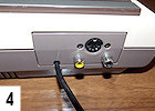
In my case I asked Gavino to put the holes in the small panel where the
antenna cable and power socket are fastened.
Please notice that on the Hanimex Rameses and Funvision panels, there's enough
room for two RCA sockets only, whilst on the CreatiVision panel there's
even less room; you can place no more than one single output. In this
case I suggest you install a 4-pole 3.5mm video/audio socket (not RCA).
You may even want to place the sockets elsewhere on the console case,
for example on the left side of the antenna/power panel, or on the top.
This is also the time to decide whether you want mono or dual
mono audio output, how many cables or sockets, and which socket model you want
to use. You need to know this now because you have to write down the items
on your shopping list then go out and buy them.
The last thing you need to think about is the shielding of
the video and audio signals. Since the cable(s) you're adding will run
close to the RF modulator and many other analog devices including the power
circuitry (which causes a lot of interference), it/they must be shielded in
order to preserve the quality of the signals.
I suggest you get a cable with braided shield having a single or two
separate shields, depending on which version you want; panel mount sockets or
pass-through cable with female sockets.
4) NEEDED COMPONENTS AND PARTS
Whichever mod you want to do, buy either of these two cables:
- 1x 2-pole shielded cable (3 poles total) (1) if
you want the panel-mount sockets;
- 1x double thick-sleeved shielded cable if you want the pass-through cable
cable.
Variant with mono output:
- 2x RCA panel mount (2) or cable mount
(3) sockets. Colours: 1x yellow, 1x black;
- 1x RCA single-to-double adaptor on jack (4) or cable
(5). Type: 1x male in, 2x female out;
- 1x RCA cable with three male jacks per side (yellow, white and red)
(6).
Variant with dual mono output via three RCA sockets:
- 3x RCA panel mount (2) or cable mount
(3) sockets. Colours: 1x yellow, 1x white, 1x red;
- 1x RCA cable with three male jacks per side (yellow, white and red)
(6).
Variant with dual mono output via a single 4-pole
socket:
- 1x 3.5mm panel mount (7) or cable mount
(8) 4-pole socket;
- 1x 3.5mm jack-to-RCA cable (4-pole male jack on one side, male RCA jacks on
the other side)
(9).
For the consoles based on PCB model "700305" and "700319",
you may also need:
- 1x transistor type 2SC9014, Hfe classification C or D
(10).
    
    
[click pictures to enlarge]
5) TUTORIAL NO.1 (valid on PAL consoles
only)
This mod was successfully done and tested on a console with PCB model
"700319" and should work fine on consoles with PCB model "700305" (older).
Gavino took the video signal from the emitter of the "Q1"
transistor, which amplifies the signal between the TBA520 (PAL
demodulator) and the "VR3+R/C" filter group and connected it to the RF
modulator.
Taking the signal before the filter group is useful to get it at
full amplitude (unfiltered), hence it's optimal to be sent to a TV via
a direct cable.
The "Q1" transistor is model "2SC9014" and is available with
several Hfe classifications (A, B, C and D). You usually find type A on the
console, which doesn't guarantee an suitable pre-amplification level for the
composite video output. Get the datasheet here.
When testing your mod, if you notice that the picture on the TV
is distorted or the quality is too low, you should check the amplifier
transistor ("Q1") carefully. If needed, replace it with another one of higher
Hfe classification, either C or D. The higher the better: D is the best
one, though hard to find. C is also OK by the way.
A few words about the relation between the trimmer settings and
this specific mod; the setting of the VR3 trimmer (which sets the
luminance component) doesn't affect the newly added composite video
output. Tuning it is still important to get a perfect video signal over
the antenna cable only.
About the audio signal, it's taken from the "audio in" pin of
the RF modulator. That's pin no.3.
Get the Astec UM1285-8 (RF modulator) datasheet here.
The ground, which is common to both video and audio outputs, is
taken from any place on the PCB where ground is present. You can solder the
ground wire (the braided shield of the 3-pole cable) to the metal case of the
RF modulator or on a ground pad on the PCB in close proximity to where the
other soldering points are.
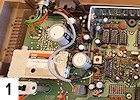
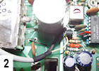
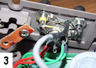
Please refer to the following pictures for full details.
    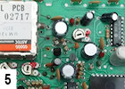
[click pictures to enlarge]
6) TUTORIAL NO.2 (valid on all PAL and NTSC
consoles)
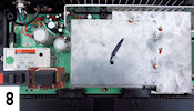
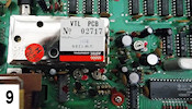
Thomas went in a different, much simpler way than Gavino. He simply took the
video and audio signals from the "video in" and "audio in" pins of the RF
modulator.
He soldered the video wire to pin no.1, the audio wire to
the pin no.3, and the ground to the metal case of the RF
modulator.
You may prefer to solder the ground wire to any of the ground pads on the
PCB.
Get the Astec UM1285-8 (RF modulator) datasheet here.
Please refer to the following pictures for full details.
[click pictures to enlarge]
7) CREDITS
Thanks very much to Gavino Sechi and Thomas Gutmeier for
providing all the precious information included in this tutorial!
Thanks very much to Paul Nicholls, The Guru and
Gavino Sechi for helping me (a lot!) clean up and re-word large parts
of the tutorial in English.
[Last updated: 22 April 2013]
|

